Camshaft and valvetrain basics
The flow capability of the cylinder heads, intake passages and exhaust passages in a 4-stroke ("Four-Cycle") engine is extremely important to engine performance. However, the motion of the valves relative to the position and velocity of the piston is perhaps even more important in determining the power a given configuration can produce.
The valve motion is generated by the shape of the cam lobes, pushing on a cam follower, and connected to the valve by one of several mechanisms, including a pushrod and rocker arm, and overhead cam configurations which operate the valves directly from the cam follower ("direct-acting") or by means of any of several different rocker arm implementations.
The configuration we will discuss here is the pushrod / rocker-arm mechanism, used in domestic automotive engines since the early part of the 20th century, and which began to dominate domestic production V8 engines beginning in 1949 (the Oldsmobile "Rocket" 324 cubic inch V8). Because of its inherent cost effectiveness, the pushrod / rocker arm OHV V8 is still used in many current engines. The following picture (courtesy of Ford Motor Company ) shows the components in this mechanism.
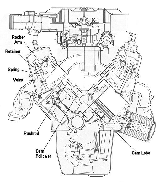
As the cam lobe rotates, it imparts linear motion to the cam follower (aka "lifter", aka "tappet"). That motion is transmitted to the pushrod, then through the rocker arm to the valve. It is clear from the picture that the cam lobe is only able to directly control the opening portion of the valve motion, by pushing the follower away from it. After the follower has reached maximum lift, it is the job of the spring, through the rocker arm and pushrod, to keep the lifter in contact with the cam lobe in order that the closing portion of the valve motion is what is programmed on the cam lobe.
Given the inherent limitations of that layout at high engine speeds, it is a huge tribute to the skills and knowledge of the NASCAR engine builders at the "Cup" level that they have succeeded in making this type of engine (358 cubic inch, pushrod / rocker-arm, two-valve-per-cylinder, normally aspirated, single-carburetor V8) operate reliably at over 10,000 RPM and produce unheard-of power levels (over 830 HP). This section will explain some of the very challenging problems involved in designing a reliable, high-performance valvetrain. The principles discussed apply to the other configurations.
The reason we focus on this configuration is that, with respect to aircraft engines, we think this pushrod / rocker-arm system is the best solution to the compromises required to achieve a good aircraft engine: (a) maximum power per pound of engine weight, combined with (b) reasonable piston speeds and valvetrain stresses for maximum reliability.
There is little question that an engine with a double-overhead-cam (DOHC) configuration and four valves per cylinder will produce more power per cubic inch of displacement. However, the additional weight of the components of that configuration and the fact that the four-valve DOHC achieves its advantage at higher engine speeds would tend to favor the pushrod / rocker arm layout.
In the early development of these engines, the max power we could coax from these engines was in the 425 HP neighborhood (which, in itself, is impressive). Today (2004) we are nearing 500 HP from these engines, while using essentially the same heads and manifolds (as specified by the NASCAR rules for these engines).
The big change has been in cam lobe profiles which are optimized to this particular flow-limited configuration. Of course, as you might expect, these cam profiles are very hard on the valve train components. Here, we will attempt to explain why, and how different requirements can be met through the various compromises taken in cam lobe design.
"Duration" is the number of crankshaft degrees of rotation during which the cam follower lift is greater than a specified value. Without knowing the lift value at which a duration is measured, the duration number is meaningless. Because the cam lobe contains slow-motion ramps at the beginning and end of the lift period to take up clearances and to get the parts into motion gradually, it has become an accepted industry practice (initiated by Harvey Crane back in the 1960's) to specify lobe duration as the number of degrees between the points at which the lifter is 0.050 off the base circle.
Overlap, referring to the graph above, is the number of degrees of crankshaft rotation during which both valves are off their seat, and measured as the number of degrees of crankshaft rotation during which both lifters are more than a specified distance from the zero-lift point (off base circle). Again, without this reference number, an overlap spec is essentially worthless. If we use the 0.050 reference, the overlap of the cam above is roughly 40 degrees. Overlap, as we will discuss later, is a very important influence on engine performance. Ed Iskenderian, one of the early developers of aftermarket camshafts, used to refer to overlap an "the 5th Cycle".
exhaust lobe has 0.420 of lift at 108 degrees before TDC and 262 degrees of duration. In this case, the cam follower is away from it's zero-motion position for 250 degrees of crankshaft rotation (125 degrees of camshaft rotation). That lobe is described as having a "duration" of 250 degrees. In this case, the valve begins to open 20 degrees before Top Dead Center (BTC) and doesn't close until 50 degrees after Bottom Dead Center (ABC). The lobe "centerline" (the point of max lobe lift) is located at 105 degrees after TDC. To find the centerline, assume the max lobe lift occurs at the half-duration point (which is not necessarily so, but close enough for the purposes of this presentation). Since the valve opens 20° BTC, then the max lift (half-duration point, 125 ° of crankshaft travel) occurs at 125-20 = 105° after TDC.
Now, as you might expect, it can be difficult to determine, with sufficient accuracy, the exact crankshaft position when a valve begins to open or close. And, the exact value of the crankshaft position can be dramatically changed by changes in clearance between the valve and the mechanism which moves it (rocker arm or cam follower).
That situation is not much improved if, instead of valve motion, you use lifter motion to determine these points. The reason is because a cam lobe does not start the lifter moving suddenly. Each cam lobe includes opening and closing "ramps" which allow the cam to start and to end the lifter motion in a gradual fashion. Therefore, the contemporary method of specifying cam lobe events is to state the number of degrees before and after TDC / BDC at which the lifter has moved to a distance of 0.050" from it's zero-motion position. The "zero motion position" is measured when the maximum lift portion of the cam lobe is opposite (180° away from) the lifter (known as the "base circle" or "heel" of the lobe).
The next curve shows the cam follower velocity (red curve) which corresponds to the cam follower lift curve (blue).
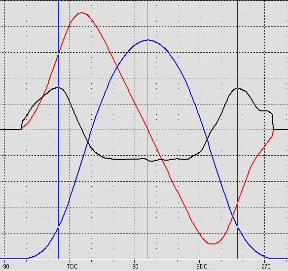
The next curve shows the cam follower acceleration (black) and velocity (red) which corresponds to the cam follower lift curve (blue).
The following graph shows the lifter motion caused by two different cam lobes, both of which have the same opening and closing specifications (as measured by the 0.050" travel points of the lifter). These plots are known as "lift curves". The horizontal axis is crankshaft rotation, referenced to TDC and BDC.
As you can see, both lift curves look fairly smooth. However, there is a substantial difference between the amount of force and vibration each of these two lobes impose on the remainder of the valvetrain they operate. Those differences can only be seen by examining the curves which show the velocity and the acceleration these lobes generate.
The valve motion is generated by the shape of the cam lobes, pushing on a cam follower, and connected to the valve by one of several mechanisms, including a pushrod and rocker arm, and overhead cam configurations which operate the valves directly from the cam follower ("direct-acting") or by means of any of several different rocker arm implementations.
The configuration we will discuss here is the pushrod / rocker-arm mechanism, used in domestic automotive engines since the early part of the 20th century, and which began to dominate domestic production V8 engines beginning in 1949 (the Oldsmobile "Rocket" 324 cubic inch V8). Because of its inherent cost effectiveness, the pushrod / rocker arm OHV V8 is still used in many current engines. The following picture (courtesy of Ford Motor Company ) shows the components in this mechanism.
As the cam lobe rotates, it imparts linear motion to the cam follower (aka "lifter", aka "tappet"). That motion is transmitted to the pushrod, then through the rocker arm to the valve. It is clear from the picture that the cam lobe is only able to directly control the opening portion of the valve motion, by pushing the follower away from it. After the follower has reached maximum lift, it is the job of the spring, through the rocker arm and pushrod, to keep the lifter in contact with the cam lobe in order that the closing portion of the valve motion is what is programmed on the cam lobe.
Given the inherent limitations of that layout at high engine speeds, it is a huge tribute to the skills and knowledge of the NASCAR engine builders at the "Cup" level that they have succeeded in making this type of engine (358 cubic inch, pushrod / rocker-arm, two-valve-per-cylinder, normally aspirated, single-carburetor V8) operate reliably at over 10,000 RPM and produce unheard-of power levels (over 830 HP). This section will explain some of the very challenging problems involved in designing a reliable, high-performance valvetrain. The principles discussed apply to the other configurations.
The reason we focus on this configuration is that, with respect to aircraft engines, we think this pushrod / rocker-arm system is the best solution to the compromises required to achieve a good aircraft engine: (a) maximum power per pound of engine weight, combined with (b) reasonable piston speeds and valvetrain stresses for maximum reliability.
There is little question that an engine with a double-overhead-cam (DOHC) configuration and four valves per cylinder will produce more power per cubic inch of displacement. However, the additional weight of the components of that configuration and the fact that the four-valve DOHC achieves its advantage at higher engine speeds would tend to favor the pushrod / rocker arm layout.
INTRODUCTION
Basic camshaft events (valve opening, closing and max lift) are commonly referenced to crankshaft position, because the motion of the valves needs to be studied relative to the position (and velocity) of the piston. For example, a typical intake lobe might begin to open the valve at 20 degrees Before Top Center (BTC, before the piston reaches the exact top of its stroke) and to close the valve at 50 degrees after Bottom Dead Center (BDC). And yes, the piston HAS reversed direction at BDC and is on its way up when the intake valve actually closes. This, and other apparent anomalies, are related to the dynamics of air motion, and will be discussed later.CAM LOBES
An excellent example of the influence which cam lobe profiles have on performance is the evolution of what are known as "restricted" race engines. These engines are "restricted" with respect to the modifications that can be done to them, in an effort to limit the power, hence the cost of the engines. The most common engine in this category is an iron-block 355-cubic inch small-block Chevy (SBC) V8, which is limited to stock (unported, unmodified) cast-iron cylinder heads and intake manifold. In certain classes these engines are limited to a single two-barrel carburetor which, in stock form, can't flow more than 500 CFM of air at a pressure differential of 3" of water. This configuration represents the very incarnation of a "flow-limited" engine.In the early development of these engines, the max power we could coax from these engines was in the 425 HP neighborhood (which, in itself, is impressive). Today (2004) we are nearing 500 HP from these engines, while using essentially the same heads and manifolds (as specified by the NASCAR rules for these engines).
The big change has been in cam lobe profiles which are optimized to this particular flow-limited configuration. Of course, as you might expect, these cam profiles are very hard on the valve train components. Here, we will attempt to explain why, and how different requirements can be met through the various compromises taken in cam lobe design.
CAM FOLLOWER MOTION
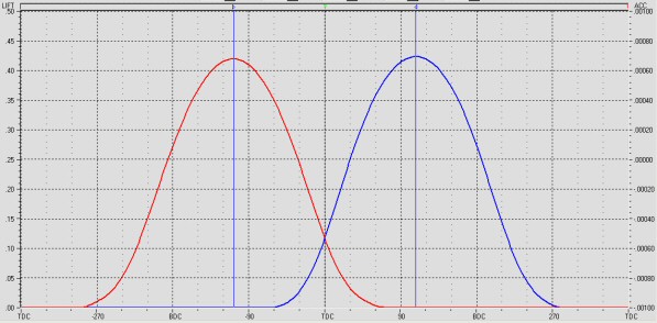
Here is a graph showing the motion of the cam followers for one cylinder of a two-valve (intake and exhaust) pushrod-rocker arm engine as a function of lobe rotation. Note that the rotation axis is plotted in degrees of crankshaft rotation (which is twice the camshaft rotation, since the camshaft spins at half crankshaft speed in a 4-stroke engine). Notice also that the lobe lift is roughly 0.420 inches, which with a nominal rocker ratio of 1.6, will theoretically produce nearly 0.675 of valve lift. The red trace is the exhaust follower travel and the blue trace is the intake follower travel. Cam Follower Motion
The commonly-quoted specifications for cam lobes are lift, duration, overlap, and lobe separation. The "Lift" spec is the maximum amount of travel the cam follower experiences as the cam lobe rotates under it. The "zero lift point" can be defined as the lift when the lobe is rotated 180 degrees from its maximum lift point, when the cam follower is said to be "on the base circle" of the lobe (the constant-radius portion of the lobe)."Duration" is the number of crankshaft degrees of rotation during which the cam follower lift is greater than a specified value. Without knowing the lift value at which a duration is measured, the duration number is meaningless. Because the cam lobe contains slow-motion ramps at the beginning and end of the lift period to take up clearances and to get the parts into motion gradually, it has become an accepted industry practice (initiated by Harvey Crane back in the 1960's) to specify lobe duration as the number of degrees between the points at which the lifter is 0.050 off the base circle.
Overlap, referring to the graph above, is the number of degrees of crankshaft rotation during which both valves are off their seat, and measured as the number of degrees of crankshaft rotation during which both lifters are more than a specified distance from the zero-lift point (off base circle). Again, without this reference number, an overlap spec is essentially worthless. If we use the 0.050 reference, the overlap of the cam above is roughly 40 degrees. Overlap, as we will discuss later, is a very important influence on engine performance. Ed Iskenderian, one of the early developers of aftermarket camshafts, used to refer to overlap an "the 5th Cycle".
exhaust lobe has 0.420 of lift at 108 degrees before TDC and 262 degrees of duration. In this case, the cam follower is away from it's zero-motion position for 250 degrees of crankshaft rotation (125 degrees of camshaft rotation). That lobe is described as having a "duration" of 250 degrees. In this case, the valve begins to open 20 degrees before Top Dead Center (BTC) and doesn't close until 50 degrees after Bottom Dead Center (ABC). The lobe "centerline" (the point of max lobe lift) is located at 105 degrees after TDC. To find the centerline, assume the max lobe lift occurs at the half-duration point (which is not necessarily so, but close enough for the purposes of this presentation). Since the valve opens 20° BTC, then the max lift (half-duration point, 125 ° of crankshaft travel) occurs at 125-20 = 105° after TDC.
Now, as you might expect, it can be difficult to determine, with sufficient accuracy, the exact crankshaft position when a valve begins to open or close. And, the exact value of the crankshaft position can be dramatically changed by changes in clearance between the valve and the mechanism which moves it (rocker arm or cam follower).
That situation is not much improved if, instead of valve motion, you use lifter motion to determine these points. The reason is because a cam lobe does not start the lifter moving suddenly. Each cam lobe includes opening and closing "ramps" which allow the cam to start and to end the lifter motion in a gradual fashion. Therefore, the contemporary method of specifying cam lobe events is to state the number of degrees before and after TDC / BDC at which the lifter has moved to a distance of 0.050" from it's zero-motion position. The "zero motion position" is measured when the maximum lift portion of the cam lobe is opposite (180° away from) the lifter (known as the "base circle" or "heel" of the lobe).
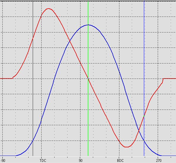
The next curve shows the cam follower velocity (red curve) which corresponds to the cam follower lift curve (blue).
The next curve shows the cam follower acceleration (black) and velocity (red) which corresponds to the cam follower lift curve (blue).
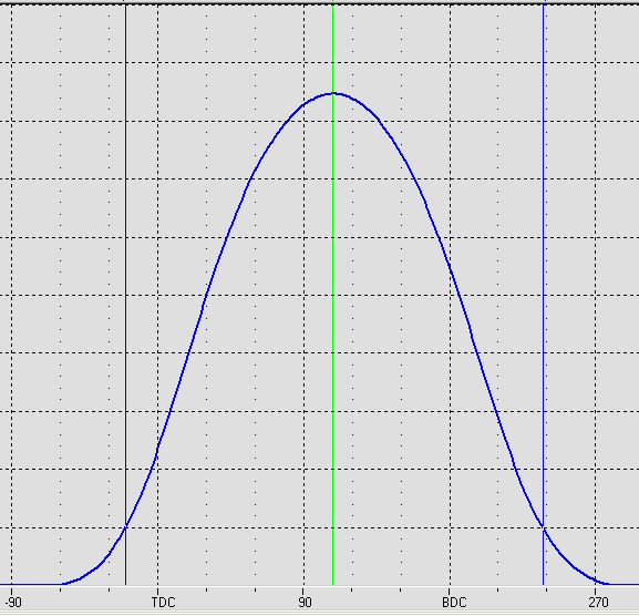
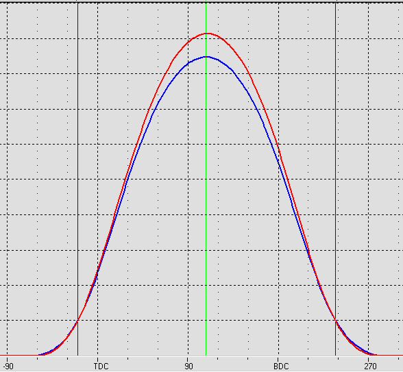
The following graph shows the lifter motion caused by two different cam lobes, both of which have the same opening and closing specifications (as measured by the 0.050" travel points of the lifter). These plots are known as "lift curves". The horizontal axis is crankshaft rotation, referenced to TDC and BDC.
As you can see, both lift curves look fairly smooth. However, there is a substantial difference between the amount of force and vibration each of these two lobes impose on the remainder of the valvetrain they operate. Those differences can only be seen by examining the curves which show the velocity and the acceleration these lobes generate.


Comments
Post a Comment